|
|
|
|
|
|
To understand Beamforming, let us take a simplified case of 4 receiver antenna elements separated by equal distance of half wavelength.
Total reception is addition of receptions from individual receiver antenna elements.
If antenna elements happen to be perpendicular to the transmitted waves, best reception is achieved as shown in figure below.
If we realign (tilt) antenna elements (as shown in figure below) by angle (θ),
receptions from individual antenna elements start canceling each other.
At certain value of θ, (theoretically) there will be zero reception.
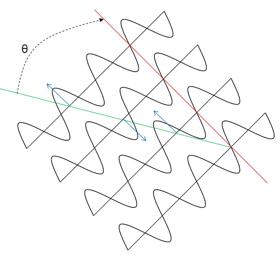
Fig "Antenna elements"
Realigning antenna elements has basically forced each antenna element to receive delayed wave
compared to its predecessor antenna element by constant value, say Δt.
If you notice, Δt is dependent on θ and can be calculated as, Δt = π sin(θ).
If rk is received signal at kth antenna element, we get
R = ej. r1 + ej.π.sinθ. r2 + ej.2.π.sinθ. r3 + ej.3.π.sinθ. r4 = Σ (ej.(k-1).π.sinθ. rk)
If we plot amplitude Vs θ (-90 to +90), it will give us our famous beam lobes, as shown below (8 antenna elements).

Fig "Beam lobes"
|
|
|
|
|
|
|
|
|
|

